Circuit Diagram Generator Avr
The diagram below shows a generic AVR implementation. This type of circuit has been around for years. Its numerous variations are found in both portable generators and automotive alternators and are described in various patents, such as General Motor's US3376496 for 3-phase applications and Honda's US6522106 .

A more effective approach for developing ACAC automatic voltage regulators
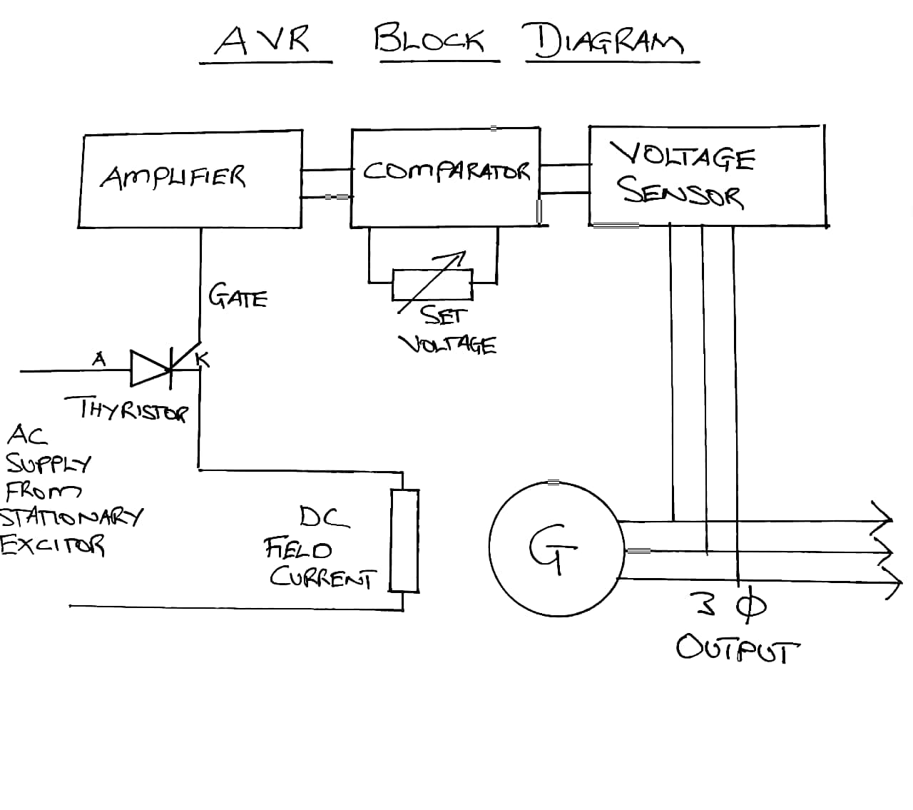
Automatic Voltage Control - Figure 8.20 gives the schematic diagram of an automatic voltage regulator of a generator. It basically consists of a main exciter which excites the alternator field to control the output voltage.
Voltage Regulator Working Principle & Circuit Diagram Voltage Regulator in Power Supply
The automatic voltage regulator is used to regulate the voltage. It takes the fluctuates voltage and changes them into a constant voltage. The automatic voltage regulator works on the principle of detection of errors. It controls the voltage of the system and has the operation of the limit nearer to the steady state stability.
Integral Voltage Regulator Wiring Diagram
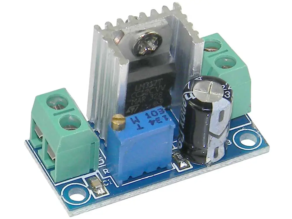
1. A general positive voltage regulator - The output voltage can be adjusted by varying the pot and resistor. There is an equation given to calculate V0ut. 2. Adjustable voltage regulator circuit - where the output voltage can be selected digitally.
regulator circuit diagram Wiring Diagram and Schematics
An automatic voltage regulator circuit is a handy electronic device that ensures a steady and optimum voltage supply, protecting the devices from damage caused by under or overvoltage scenarios. In this article, we will guide you through the process of building your own automatic voltage regulator circuit, complete with a detailed diagram.
Voltage Regulator Working Principle & Circuit Diagram Voltage Regulator in Power Supply
Download scientific diagram | Automatic Voltage Regulator (AVR) Circuit Scheme. from publication: Automatic Voltage Regulator as a Voltage Control in 1 Phase Axial Generator.

[PDF] Single Phase Automatic Voltage Regulator Design for Synchronous Generator Semantic Scholar
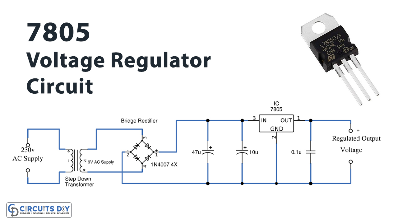
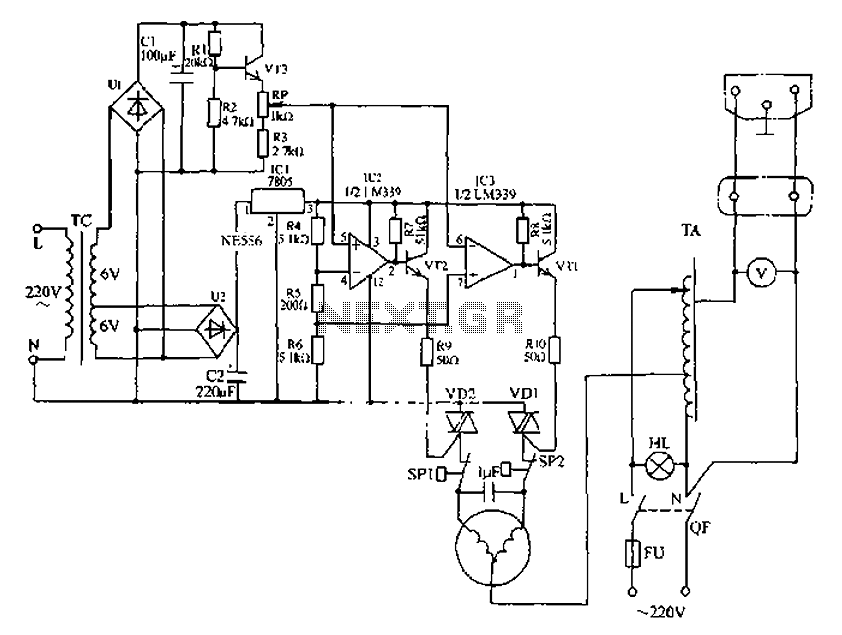
Circuit Operation: The Mains 120V AC Line and Neutral contains a switch and a fuse up to 10A. The DPDT Switch is used for Voltage up and Down. DPDT Switch has a four ends. The Neutral from mains enters directly in first end of DPDT and the Line/Phase enters the transformer primary winding which is of 220 Turns of 6 layers.
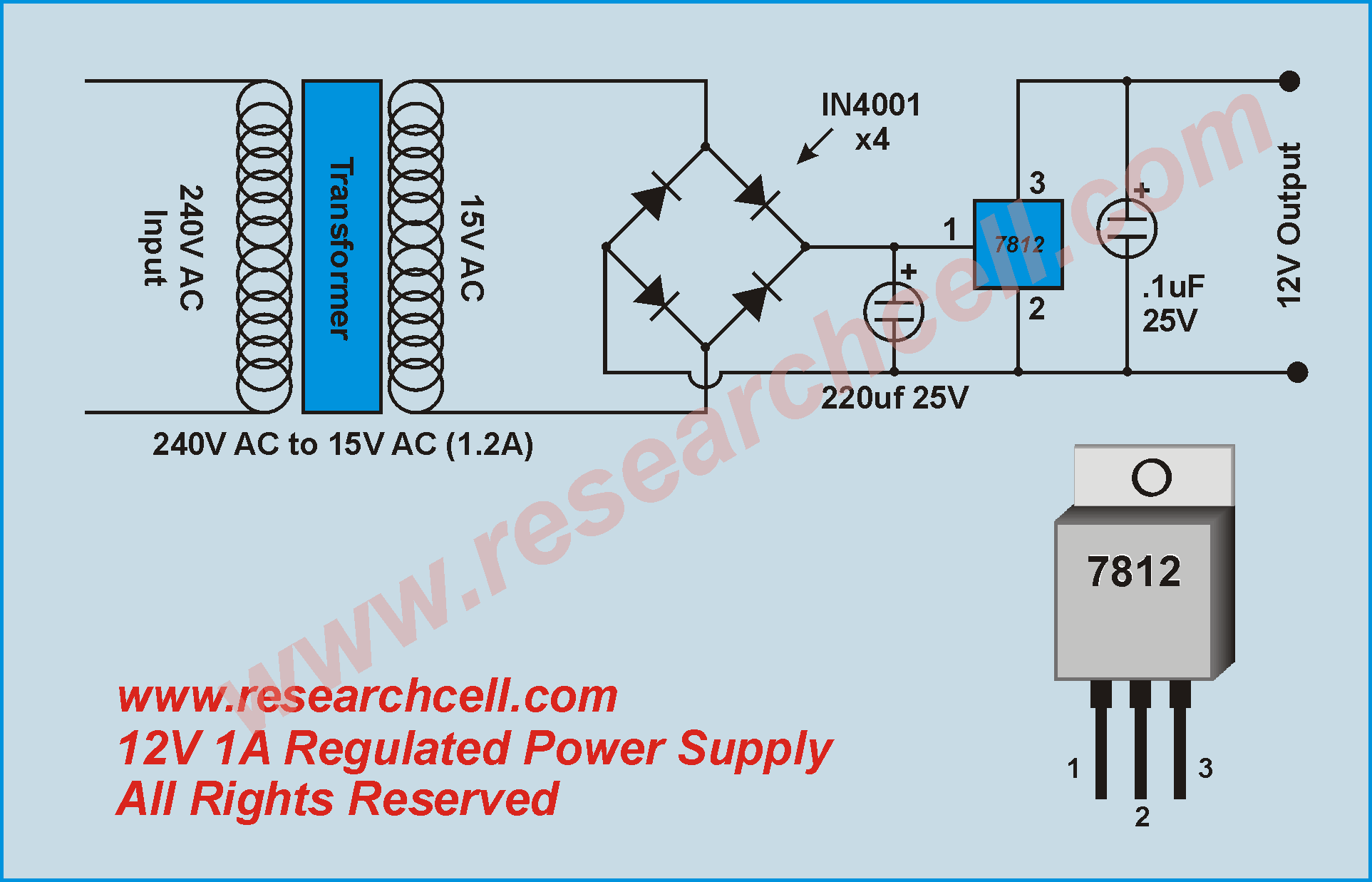
12 Volt Dc Voltage Regulator Circuit Diagram Pdf Wiring Diagram
Basically the AVR or Automatic Voltage Regulators function for generator is to ensure voltage generated from power generator running smooth to maintain the stable voltage in specified limit. It can stabilize the voltage value when suddenly change of load for power supply demand.
Automatic AC voltage regulator circuit under Power Supply Circuits 59563 Next.gr
GENERAL INFORMATION 1.1 DESCRIPTION EA63-5 is an automatic voltage regulator (AVR) for AMG synchronous generator industrial application series. The AVR is typically supplied by a single-phase auxiliary winding wound into the stator slots. It also can be supplied by permanent magnet generator ˄PMG˅or phase voltage of main terminal. 1.2 SPECIFICATION

Schematic Diagram Automatic Voltage Regulator Wiring Diagram
A voltage regulator is designed to automatically 'regulate' voltage level. It basically steps down the input voltage to the desired level and keeps that in that same level during the supply. This makes sure that even when a load is applied the voltage doesn't drop. Thus, a voltage regulator is used for two reasons:-
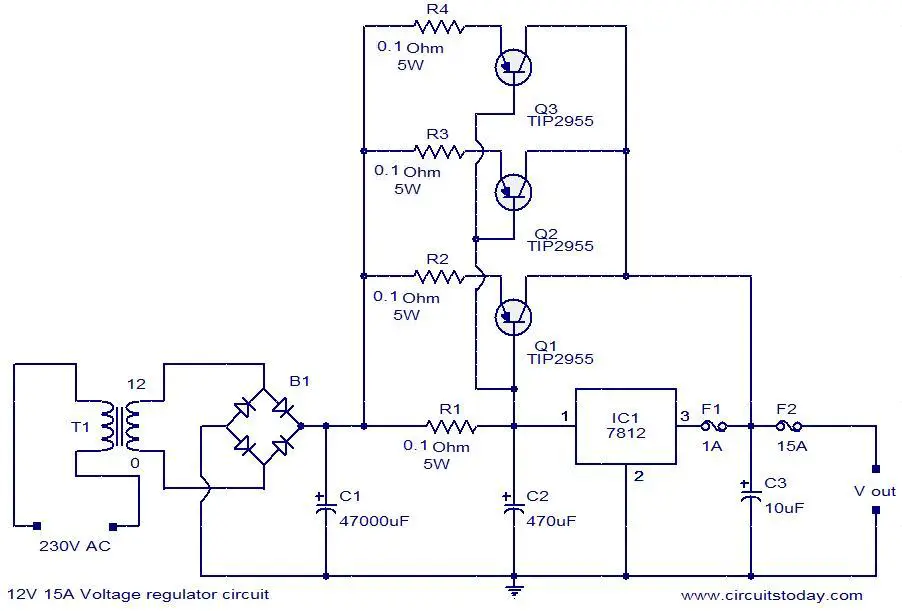
How to Make Voltage Regulator Circuits Circuit Basics
Working, limiters & other components of AVR (Automatic voltage regulator) has been illustrated with the help of block diagrams & circuit diagrams.Easy detail.
Understanding Voltage Regulation in Power Supply Voltage Regulator Circuit Diagram
Mecc Alte Automatic Voltage Regulators (AVR Regulator) set the precedent for AVRs in a range of industries around the world, read more here.. Management of temporary short circuits (start up of asynchronous motors) Open collector output (not insulated) signalling intervention of protective devices (insulation on optional DI1 module) with.
Schematic Automatic Voltage Regulator Wiring Diagram
Figure 1. Complete power supply circuit with the load resistor. First, the load resistor serves as a bleeder. A bleeder allows charged capacitors to drain. During operation of a power supply, peak voltages are stored in the capacitors of the filter sections. These capacitors remain charged after the equipment is turned off.
Automatic Ac Voltage Regulator Circuit Diagram
MX341 is a two phase sensed Automatic Voltage Regulator and forms part of the excitation system for a brush-less generator. Excitation power is derived from a three-phase permanent magnet generator (PMG), to isolate the AVR control circuits from the effects of non-linear loads and to reduce radio frequency interference on the generator terminals.

Schematic Diagram Of Automatic Voltage Regulator Of Ac Wiring Diagram
An automatic voltage regulator schematic circuit diagram is an important tool for electrical engineers to understand how electricity works and how to maintain proper electric current levels. The regulator helps to protect against power fluctuations and prevent overloading of circuits, making it an essential part of any electrical system.
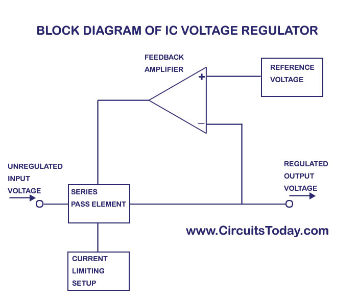
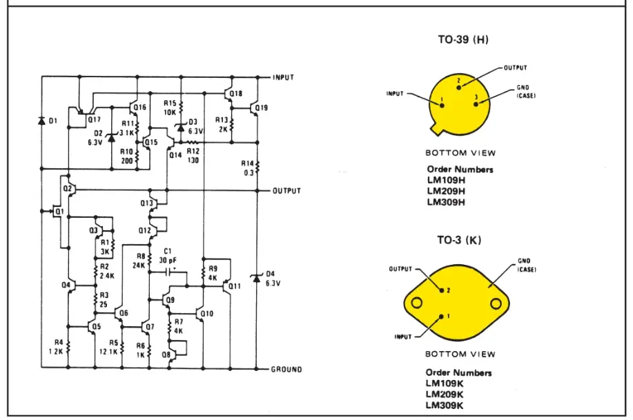
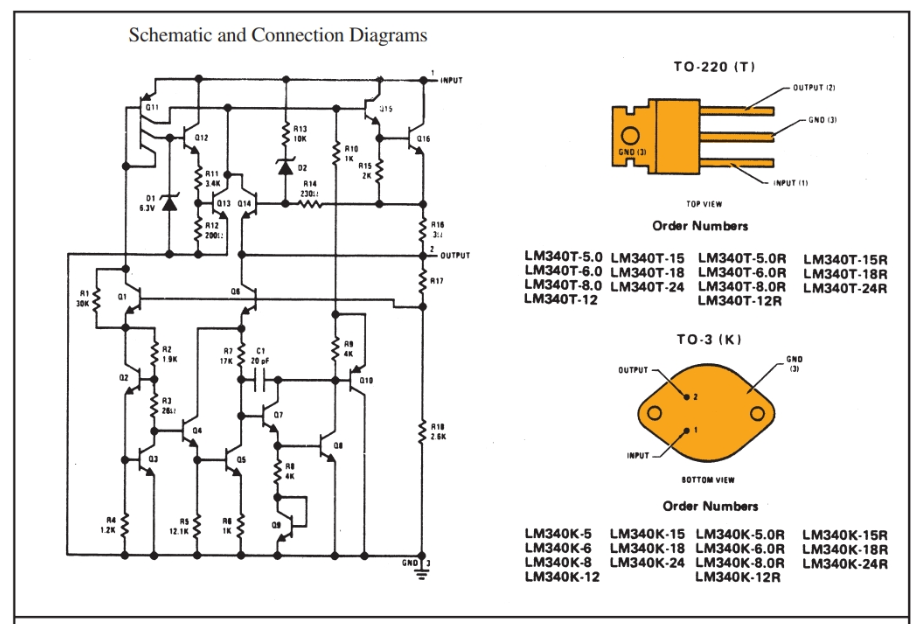
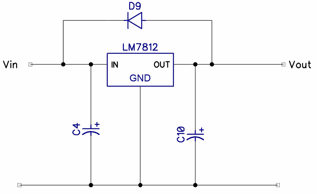
IC Voltage Regulatorswith Circuit Diagram Design & Theory
A voltage regulator is a system designed to automatically maintain a constant voltage. It may use a simple feed-forward design or may include negative feedback. It may use an electromechanical mechanism, or electronic components. Depending on the design, it may be used to regulate one or more AC or DC voltages.